


Existing buildings rarely behave like the drawings suggest. Walls shift over time, MEP routes change during renovations, structural members get modified, and years of tenant improvements leave behind conditions that no one documented properly. This is why point cloud to BIM conversion in US has become an important part of renovation, retrofit, facility management, and design projects. A laser scan captures the building as it exists today, while a well-developed BIM model turns that captured reality into usable digital information for architects, engineers, contractors, and building owners.
However, converting a point cloud into a BIM model is not simply a matter of importing scan data into Revit. The final model can be accurate enough for design coordination or unsuitable for construction decisions, depending on how the project is planned and executed. Accuracy and cost are closely connected, but they are not controlled by one factor alone. Building size, scan quality, modeling scope, required level of development, site conditions, and quality-control expectations all influence the outcome.
What Point Cloud to BIM Conversion Means
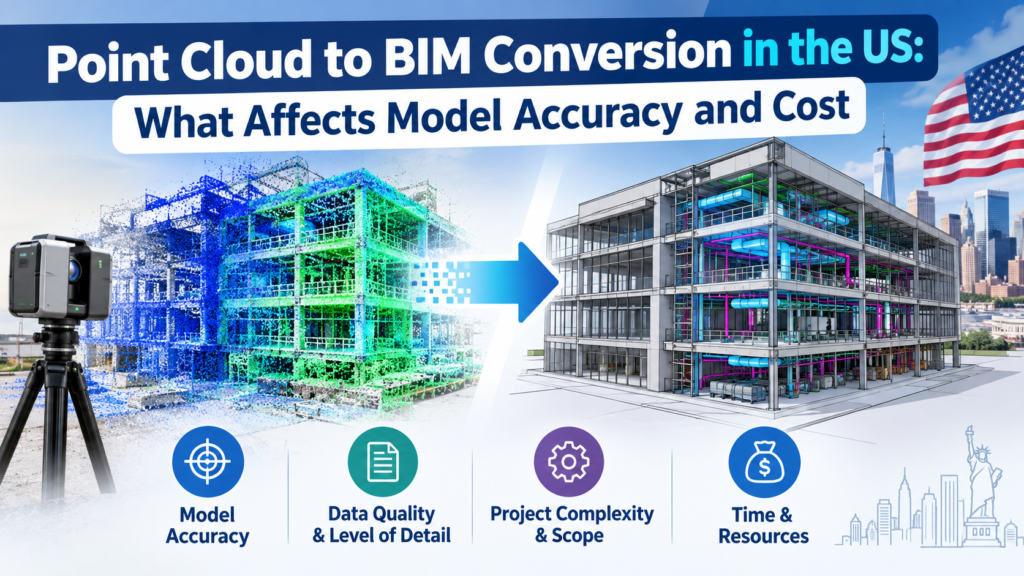
Point cloud to BIM conversion is the process of transforming laser-scanned data into a structured 3D BIM model. During a site scan, terrestrial laser scanners or mobile mapping systems capture millions of measurement points from the existing building. These points create a detailed digital representation of walls, floors, ceilings, columns, beams, openings, equipment, and visible MEP components.
The point cloud itself is valuable, but it is not always easy for a design or construction team to use. It contains raw geometric data rather than intelligent building elements. A BIM model, on the other hand, represents walls as walls, ducts as ducts, pipes as pipes, and structural members as recognizable Revit or IFC-based objects. This makes the model useful for design development, clash coordination, quantity takeoffs, renovation planning, and facility documentation.
For US projects, the purpose of the model should be clear before conversion begins. A model prepared for architectural space planning does not need the same depth as a model intended for MEP coordination or fabrication. Defining the end use early prevents unnecessary modeling work and helps the team focus on the information that will actually support project decisions.
Scan Quality Comes First
The quality of the point cloud has a direct impact on the quality of the final BIM model. A scan with strong coverage, consistent density, and minimal noise gives the modeling team reliable reference data. In contrast, incomplete scans, dark surfaces, reflective materials, glass, moving objects, and inaccessible areas can create gaps or distortions that make interpretation difficult.
Scanner capability matters, but it is not the only factor. The person operating the equipment needs to select suitable scan positions, maintain proper overlap between scans, and account for challenging site conditions. A building with complex geometry, multiple levels, congested mechanical rooms, or restricted access usually requires more scan positions and more careful planning.
Registration is another critical stage. Individual scans must be aligned accurately into one coordinated point cloud. Even a small registration error can create misalignment between floors or building sections, which later affects wall positions, structural alignment, and MEP routing in the model. A clean registration process reduces the chance of carrying errors into the BIM deliverable.
Typical scan-to-BIM accuracy expectations often fall in a range of roughly 5 mm to 15 mm, though the appropriate tolerance depends on the project requirement and the condition of the captured data. The final accuracy is not determined by the scanner alone; it is the combined result of scanner performance, registration quality, modeling tolerance, and the way irregular surfaces are interpreted into parametric model elements.archilance+1
Building Complexity Changes Everything
A small, open commercial space is much simpler to model than a multi-storey hospital, industrial plant, or occupied office building with layered renovations. Larger floor areas require more scan positions, more data processing, and more modeling hours. Complexity increases the work even when the square footage remains the same.
Mechanical, electrical, and plumbing systems are among the biggest drivers of complexity. Exposed ductwork, piping, cable trays, equipment, valves, and ceiling-mounted services take considerably more time to identify and model than basic architectural elements. In dense mechanical rooms, the modeling team may need to distinguish between similar-looking components, verify routing directions, and interpret connections that are partially hidden from the scanner.
Older buildings add another layer of difficulty. Uneven walls, non-orthogonal geometry, deteriorated finishes, undocumented alterations, and irregular structural framing cannot always be represented perfectly with standard Revit families. The team may need to use custom families, simplified representations, or separate reference geometry. These decisions should be documented so the client understands what the model includes and what it intentionally simplifies.
Multi-storey buildings, basements, roofs, façades, and exterior site features also expand the scope. Each additional area increases the number of scans, the size of the point cloud, and the hours required for cleanup, registration, modeling, and quality checks.
LOD Determines the Modeling Effort
Level of Development, commonly called LOD, is one of the most important factors affecting both accuracy expectations and cost. LOD is not just a measure of visual detail. It defines how reliable a model element is in terms of geometry, location, size, orientation, and associated information.txdot+1
At lower levels, an element may act as a placeholder or approximate representation. At LOD 300, elements generally include accurate quantity, dimensions, orientation, location, and data comparable with traditional construction documentation. LOD 350 introduces coordination-level relationships with nearby or connected elements, while LOD 400 supports fabrication-level detail.engstandards.lanl+1
For an existing-building conversion, LOD 300 is often suitable for architectural documentation, early design, estimating, and general coordination. But a project involving detailed MEP coordination, equipment replacement, or fabrication may require higher development for selected systems. The important point is that LOD should match the intended BIM use rather than being selected because it sounds more advanced.
A higher LOD increases cost because it demands more modeling time, more family development, more checking, and more coordination with project stakeholders. Moving from LOD 300 to LOD 350 can increase BIM modeling cost by approximately 30 to 50 percent, especially when MEP density is high. The right approach is to apply higher LOD only to the elements that genuinely need it, rather than modeling the entire building at the highest possible level.iscano
Scope and Deliverables Affect Price
Two projects with the same building size can have very different costs if their deliverables differ. One client may need an architectural shell model with walls, floors, roofs, doors, windows, and major structural elements. Another may need a fully coordinated model that includes architectural, structural, mechanical, electrical, plumbing, and fire-protection systems.
The scope should clearly define the disciplines to be modeled, the elements to include or exclude, the required file format, and the level of information attached to model objects. A model that includes object classification, annotations, custom parameters, space data, or compatibility with a client’s Revit standards requires additional work.arrival3d
The following scope decisions commonly affect pricing:
- Architectural-only modeling versus multi-discipline modeling
- Inclusion of MEP systems and equipment
- LOD requirements for each element category
- Custom Revit family development
- Point cloud cleanup, registration, and colorization
- QA/QC reports, model audits, and revision cycles
- Delivery in Revit, IFC, Navisworks, AutoCAD, or other formats
A detailed scope protects both parties. It gives the service provider a clear production boundary and gives the client a realistic understanding of what will be delivered.
Cost Is Driven by Modeling Hours
Many people assume laser scanning is the most expensive part of a scan-to-BIM project. In reality, field capture is often a smaller portion of the budget. The majority of cost usually comes from manual modeling, interpretation of scanned conditions, family creation, quality control, and revisions.iscano
The modeling team must review the point cloud carefully, identify building elements, create or adapt families, maintain correct locations, and check the model against the scan data. This work cannot be fully automated. Software can assist with object recognition and workflow efficiency, but human judgment remains essential for existing buildings, especially where geometry is irregular or systems are congested.
Project size and complexity strongly influence the final investment. One industry estimate places total US scan-to-BIM project costs anywhere from $2,500 to more than $200,000, depending on the scale and requirements of the project. Pricing guides also show that standard commercial spaces at LOD 200 or 300 may fall in a lower per-square-foot range, while MEP-heavy healthcare and industrial facilities can cost substantially more.iscano+1
Rather than focusing only on the lowest quote, project teams should compare what each proposal includes. A lower price may exclude registration, QA/QC, custom families, MEP systems, or revision support. Those missing items can become expensive later if the model does not perform as expected during design or construction.
QA and QC Protect the Investment
A point cloud to BIM model should not be delivered immediately after the last element is modeled. Quality assurance and quality control are essential steps that verify scan coverage, registration accuracy, modeling completeness, element placement, file standards, and consistency with the agreed scope.
A practical QC process includes comparing key model elements against the point cloud, checking dimensions at representative locations, reviewing MEP routing, validating levels and grids, and confirming that the model opens correctly in the required software. The team should also document assumptions, exclusions, and areas with limited scan visibility.
This step may look like an added cost, but it usually prevents larger costs later. An inaccurate model can lead to wrong design decisions, coordination conflicts, procurement errors, or rework during installation. A properly checked model gives the project team confidence that the digital representation reflects the actual building.
Choosing the Right Approach
The best point cloud to BIM conversion approach is not always the most detailed or the most expensive one. It is the approach that matches the project goal. A facility owner may need a reliable as-built model for future planning. An architect may need accurate existing conditions for renovation design. A contractor may need an MEP-coordinated model to reduce field conflicts. Each requirement calls for a different scope, tolerance, and level of development.
Before starting, the project team should agree on the building areas to scan, the systems to model, the required LOD, acceptable tolerance, deliverable format, QA process, and revision expectations. Clear communication at this stage creates a more accurate model and a more predictable budget.
Archdraw Outsourcing supports architecture, engineering, and construction firms with point cloud to BIM conversion services that focus on practical project requirements, model accuracy, and dependable delivery. By combining careful scan interpretation with structured BIM modeling and quality checks, the team helps clients turn existing-building data into BIM models that support better design and construction decisions.